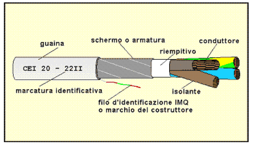
A cable is defined as the set of conductors, insulators, sheaths and armor protection or shielding, specifically built to carry the current both for energy transportation and for signal transmission.
There are three main normative references for correct use of the cables:
- CEI 20-40 “Handbook of electrical cables with operating voltage up to 450/750 V”;
- CEI 20-67 “Handbook of electrical cables with an operating voltage of 0.6/1 kV”;
- CEI 20-89 “Handbook of electrical cables with an operating voltage of 1/30 kV”.
In order to properly size an electrical cable you need to be aware of the following parameters:
- the operating voltage,
- the operating current,
- the power factor,
- the installation conditions,
- the length.
Once these parameters are known, it is up to the designer to choose the most appropriate cable for the safety and functionality of the system to be implemented, considering carefully the following features:
– Nominal voltage. Generally represented by U0/U, it is the degree of insulation of the cable. In particular, U0 is the rms value of the voltage between any conductor and the metallic coating of the cable or the ground of the surrounding environment, instead U is the rms value of the voltage between any two conductors of the cable. Under any circumstances, The maximum operating voltage of the system must not, under any circumstances, be greater than the nominal voltage of the cable;
– Current carrying capacity (Ampacity). Represented by IZ, it is the maximum intensity of current that can flow in a continuously operating cable and under certain conditions of cable-laying installation, without that the cable temperature exceeds a certain value. The ampacity of a cable is given by: IZ = IZ0 · K. IZ0 is the ampacity for a laying-cable in air at a temperature of 30°C, K is the product of the correction factors due to environmental and installation conditions. Some of these factors are for example:
- correction factor for temperatures different from 30°C;
- correction factor for grouping cables in a bundle or layer;
- correction factor for underground installation at different environmental temperatures from 20 °C;
- correction factor for depth values different from 0.8m for directly buried cables;
- correction factor for the different modes of installation.
The current carrying capacity depends on several factors including the type of insulation, the temperature of operation, the thermal exchange with the environment in which the cable is installed due to the mode of installation. For the purposes of increasing the value of the current-carrying capacity, the material with which the insulation is made, is of fundamental importance. In fact, if you use a material more heat-resistant, the allowable temperature increases, and consequently the cable has a higher currenty carrying capacity keeping constant the section. The ampacity must satisfy the relationship IZ ≥ IB, that is, it must have a value equal or greater than the operating current IB of the circuit. If you want to assess the ampacity of a cable, you should also consider the so-called “proximity effect“, consisting in the fact that each cable heats up both because of the current that runs inside and because of the heat received by the contact with the neighboring cables. For example, if several lines pass in the same protection tube, the designer or installer must consider lower ampacities in order to avoid that the temperature exceeds the operating temperature of the cable;
– Voltage drop. It is the voltage difference between the origin of the electric system and the point of use. It depends on: the phase current, the length, resistance and reactance of the line; the power factor of the user. In general, the voltage drop should be less than 4% of the value of the operating voltage of the system. If the designer assessing it valid, other values can be adopted: 3% for lighting cables; 10% for engines at start;
– Maximum operating temperature. It is the allowable operating temperature depending on the material from which is made the insulation of the conductor, and it is a value between 60 and 105 ° C;
– Maximum temperature of short circuit. It is the temperature of the cable, a few moments before the intervention of the thermal protection, as a result of overheating due to a short circuit intense but short;
– Place of installation. The choice of cable is subject to any specific rules concerning the place of installation environments such as public entertainment, places with danger of explosion, environments with higher fire hazards, construction sites, medical rooms;
– Terms of use and method of installation. CEI 64-8, part 5 deals with the selection and installation of electrical components, and especially chapter 52 refers to the selection and installation of cables according to the type of allowable installations. For example:
- sheathless cables in protective tubes enclosed in masonry;
- multicore cables in protective tubes enclosed in masonry;
- cables installed in free air;
- multicore cables in no-circular protective tubes laid on walls;
- multicore cables submerged in water;
- cables laid in perforated cable trays;
- cables laid in non-perforated cable trays;
- Single core and multicore sheathed cables in protective tubes underground or in tunnels.
With regard to the underground cable laying, it is considered direct if the cable is laid directly in contact with the ground, while it is considered indirect if the cable is laid in a underground tube, conduit or tunnel. It is also considered an underground cable laying that performed under the floor of covered places such as cellars and/or garages, if it is conceivable the presence of water for long periods. If the cable is installed in a cable tray for more than 30% of its length, it is considered placed in free air. With regard to the terms of use, the outer sheath, the insulation and the outer metal armor are relevant;
– Minimum radius of curvature. It depends on the materials used and the construction characteristics of the cable. You should pay particular attention to this parameter, because in the case of bending angles especially narrow, not complying with the requirements of the manufacturer, you can cause serious damage to the functionality and safety of the cable, especially at low temperatures.
Elements of an electric cable
An electrical cable consists of the following elements:
– The conductor is usually a complex of elementary metal wires arranged in a spiral in order to reduce the skin effect, and it is intended to conduct current. The material of the conductor can be: annealed, naked or coated copper, naked aluminum or aluminum alloy. The term “coated” means a thin layer of a metal conductor such as tin, tin alloy or lead alloy, which covers the conductor. The conductor can be a single wire (stranded wire) or rope (flexible wire), the CEI 20-29 subdivides the conductor into four classes depending on the flexibility:
- class 1: conductors for fixed installation cables, rigid, single-wire with circular cross-section;
- class 2: conductors for fixed installation cables, rigid rope, divided into non-compact of circular cross section, compact of circular cross section, sectoral;
- class 5: conductors for fixed or mobile installation, flexible;
- class 6: conductors for fixed or mobile installation, very flexible;
– The insulator is a dielectric material wrapping around the conductor and ot is designed to withstand the voltage. It is a key part of the cable that determines the performance in terms of nominal voltage, capacity and thermal behavior. It is formed by the mixture of materials appropriately selected and dosed: PVC, rubber, impregnated paper, synthetic resins. The combination of conductor and insulator constitutes the core of the cable. A cable can be composed of multiple cores;
– The belt is the wrapping insulating filler applied on all the cores and used to fill the interstices between the cores, giving a round shape. The belt is normally not used in the cables of small cross section and in those not subject to particular pressures mechanical;
– The shield consists of a thin copper strip coiled and applied on all the cores or around the insulation of each individual core. It is required for cables with a nominal voltage of ground insulation greater than 3.6 kV. The CEI regulations, for cables with a nominal voltage of ground insulation greater than 8 kV, require shielding of each core of the cable. The shield has the dual function to confine the electric field generated in the conductors when they are under tension limiting the propagation in the surrounding environment and to protect the cable from external electromagnetic disturbances;
– The outer sheath – the outer insulation – the metal armor are external coatings that protect the belt and the cable cores from mechanical and external agents. For the outer sheath and the outer insulation we use materials such as PVC, PE, rubber, other types of thermoplastic resins, textile braid, insteaqd for the metal reinforcement we use steel wires or tapes, lead or aluminum pipe.
These components, used together or separately, are decisive for the classification of the method of cable installation. They become indispensable for cables laid: in free air, underground, in the cable tray, at sight, in channels without lid, in the ceiling or under the floating floor.
How to classify cables
The electrical cables are characterized:
in function of the operating voltage:
- low voltage cable used in the category 0 and I;
- medium and high voltage cables, used in the category II and III.
in function of the type of insulation:
- cable insulated with elastomeric material, consisting of mixtures based on natural or synthetic rubber, such as ethylene-propylene rubber (EPR) and silicone;
- cables insulated with thermoplastic material, consisting of thermoplastic resins such as polyvinyl chloride (PVC) and polyethylene (PE);
- cables with mineral insulation made from magnesium oxide. They have good characteristics of resistance to fire;
- cables insulated with impregnated paper , distinguished according to the type of impregnation in normal, oil fluid, gas.
in function of their use
- cables for fixed installation. Once they are installed they will not to be moved;
- cables for mobile installation. They are subject to more or less frequent movements such as the power supply cable of a tool or of a household appliance.
in function of the number of cores
- unipolar,
- bipolar,
- tripolar,
- multipolar;
in function of their fire behavior
- flame retardant cables. These cables do not propagate the flame, if installed in vertical position (the most unfavorable position) ;
- fire retardant cables. These cables avoid the spread of fire, if installed in bundles;
- fire resistant cables. These cables provides the service even when they are directly exposed to the flames. They are intended to be used mainly in emergency circuits for alarm, lighting and communication;
- cables with low emission of smoke, toxic gases and corrosive LS0H (Low Smoke Zero Halogen). These cables guarantee visibility during the fire in order to help the evacuation of people by reducing the emission of opaque smoke and toxic gases.
depending on the label affixed by the manufacturer warranty
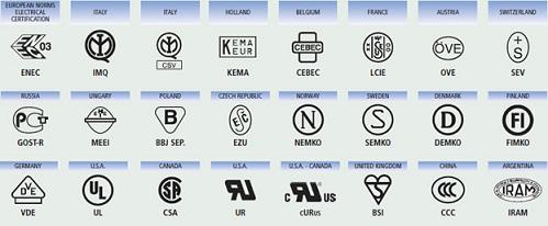
- CE is an administrative step which entered into force in 1993. The European Community requires the manufacturer to ensure compliance with the requirements of the Low Voltage Directive, so allowing the marketing of products freely within the European Union. The CE mark is made on the basis of the guarantee provided by a declaration of conformity with the requirements of the Low Voltage Directive issued by the manufacturer. The CE marking should not be confused with any markings of quality;
- IEMMEQU (Italian Quality Mark Institute) is a mark at national level, on a voluntary basis, which guarantees that the verification of design requirements and cable test is performed not by the manufacturer but by a third party, IMQ precisely. The IMQ laboratories test are equipped and approved for the verification of compliance with the IEC, CENELEC, IEC. Other quality marks at national level, on a voluntary basis are: CEBEC (Belgium), Ezu (Czech Republic), VDE (Germany), AENOR (Spain), NF (France), BASEC (Great Britain), SEV (Switzerland), OVE (Austria), Demko (Denmark), Semko (Sweden ), KWE (Poland), KEMA-KEUR (Netherlands), while are required: CCC (China), STB (Belarus), CSA (Canada), RCM (Australia), IRAM (Argentina), NOM (Mexico), PCT GOST -R (Russia), UkrSEPRO (Ukraine);
- HAR is a marking issued for the cables conforming with the CENELEC standards (European Committee for Electrotechnical Standardization) and then subjected to regular quality control guaranteed by IMQ. The mark HAR is recognized as conforming with the national standards of the following countries without further formalities neither technical nor administrative: Austria, Belgium, Denmark, Finland, France, Germany, Great Britain, Greece, Ireland, Italy, Netherlands, Norway, Poland, Portugal, Czech Republic, Spain, Sweden, Switzerland, Turkey, Hungary.
in function of their designation:
- Harmonized. They have characteristics acknowledged at European level. They are in compliance with CENELEC harmonization documents and identifiable by the HAR mark. Harmonized cables are designated with the international system according to CENELEC HD 361 (IEC 20-27).
- Non-harmonized. They have characteristics aknowledged only to a national level. They are designated with the Italian system according to the table CEI UNEL 35011.
The distribution with cables allows a great flexibility and practicality especially when the currents to be transported are high. For example, this avoids the use of cables with an excessive section and consequenlty hardly maneuverable, often not available on the market. In order to increase the current to be transferred using already existing connections, you can use cables connected in parallel. The cables in parallel are typically protected by a single switch with a nominal current equal or less than the sum of the current capacity of each cables. This is the reason why the cables in parallel must have the same section, the same length and must be made of the same material, so that the current is distributed in equal parts on each cable. Beyond a certain section, typically 70 mm2, the reactance is no longer negligible compared to the resistance; therefore you should make it uniform by arranging the cables of the same phase as symmetrical as possible with respect to the ideal center of the bundle of cables. When you’re dealing with cables, it is necessary to distinguish between those consisting of conductor and insulator and those consisting of conductor, insulation and outer sheath. A cable without a sheath can only be unipolar, while a sheathed cable can be either unipolar or multipolar.
Designation
The electrical cables are characterized by alphanumeric abbreviations established by rules. These sequences of characters are then printed on the outer sheath, usually every meter, using special indelible ink. This allows an easy identification after installation.
In particular, we use two designation systems: one relating to the harmonized cables according to CENELEC and to the national cables recognized by CENELEC in accordance with the requirements of IEC 20-27; and the other relating to non-harmonized national cables, in accordance with the requirements of table CEI UNEL 35011. The symbols for the various systems of designation can be found both in the standards (for a pee) and in the catalogs of the various manufacturers (free).( Here you can download the Prysmian catalog with all the technical specification of electrical cables and their accessories).
Designation system CEI 20-27 (CENELEC HD 361)
The designation of a harmonized cable, according to CEI 20-27 (CENELEC HD 361), is made up of various sections represented in the following table:

Example: “H07RN -F 4G10″
- H: cable conforming to the harmonized standard CENELEC HD361
- 07: nominal voltage U0/U 450/750 V
- R: insulation material in ordinary ethyl propylene rubber
- N: non-metallic sheath of polychloroprene
- none: circular cable
- none: copper conductor
- -F: stranded conductor for fixed installation
- 4G10: cable with four cores of section 10 mm2, one with a green-yellow insulator
Example: “N07G9 -K 1×25”
- N: national cable recognized by CENELEC
- 07: nominal voltage U0/U 450/750 V
- G9: insulation with a special cross-linked elastomer
- none: circular cable
- none: copper conductor
- -K: flexible conductor cable for fixed installation
- 1×25: pole cable with section 25 mm2
Designation system CEI UNEL 35011
The designation of a not harmonized cable, in accordance with IEC-35011 UNEL, must be preceded by the designation “cable” and must be composed by a succession of symbols as shown in the following table:
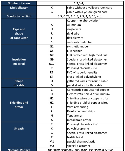
In order to complete the designation, the abbreviation must be followed by citing the table number CEI UNEL if it exists, other information or additional requirements.
Example: “cable 3G6 FG7OM1 -0,6/1 kV CEI UNEL 35382”
- 3G6: three-core cable with a cross-section of 6 mm2 , one with a yellow-green insulator
- F: stranded and round conductor
- G7: ethylene propylene rubber insulation of high modulus with a characteristic temperature of 90 °C
- O: circular cable
- M1: sheath of thermoplastic material with low emission of smoke, toxic gases and corrosive LS0H
- -0,6/1 kV: nominal voltage of insulation U0/U 0,6/1 kV
Example: “cable 4G6 FROHH2R -450/750 V”
- 4G6: cable with four cores of section 6 mm2, one with a green-yellow insulator
- F: stranded and round conductor
- R: mixture of PVC (polyvinyl chloride) with a characteristic temperature of 70°C
- H: shield of metallic-paper, paper-carbon or aluminum tape
- O: circular cable
- H2: braid or copper braid shield
- R: sheath of polyvinyl chloride (PVC)
- -450/750 V: nominal voltage of insulation U0/U 450/750 V
Reference Standards
In any technical field, particularly in the electricity sector, compliance with all relevant laws and technical standards is not a mandatory condition but it is required for the construction of plants in a workmanlike manner. A precise knowledge of technical standards is a sufficient but not mandatory prerequisite (not applying them you do not commit any offense or crime) for a proper performance of an electrical system. However it must still be done in such a way to guarantee a sufficient level of safety.
Leaving aside the legal rules, in this article we talk about all those technical rules which establish the requirements under which the electrical cables must be designed, constructed and installed. These technical standards, published by national and international institutions, may take legal value only when it is given to them by a legislative measure or when they are explicitly included in a legal contract between the parties.
In Italy by law, the requirements of electrical plants, electronic equipment and materials are set by the CEI ( Italian Electrotechnical Committee ). However, international trade and the European Union do not allow a country to adopt rules that differ from those of other countries, and for this reason, with the intent of reaching a normalization, new insitutions were set up, the IEC (International Electrotechnical Commission) which represents industrialized countries around the world, the CEN (European Committee for Standardization ) and the CENELEC (European Committee for Electrotechnical Standardization), which is the European regulatory authority for the electricity sector and to which all the national electical committees refer. In Italy the organizations in close contact with the CENELEC are the Italian Organization for Standardization (UNI), the Italian Electrotechnical Committee (IEC) and the Higher Institute of Communications and Information Technologies ( ISCOM ) .
In particular, CENELEC releases the following documentation in three official languages (English, French and German):
- documents EN (European Norm) are standards to be adopted by all the countries of the European Union, without any addition and / or modification. Any local regulations that address the same issue shall be withdrawn. In Italy, the EN standards are implemented and published by the Decree of the Ministry of Industry;
- Harmonization documents (HD Harmonization Document) do not impose any obligations on their application except that the technical content. They can be edited in the phrases and content to meet specific national requirements. They are basically reference documents which require to be introduced in the national standard within a time agreed in advance.
- Experimental standards ENV (European Norm Vorubergehend) are experimental standards with limited time of validity, during which Member States may submit their proposals. In addition to the ENV standards, the CENELEC also emits European Specification (ES) Reports (R) and Guides (G).
CEI standards
The CEI standards are normative documents drawn up, approved and published by the CEI in order to provide operators operating in particular areas with technical guidelines.
CEI-UNEL standards
The CEI-UNEL standards are publications containing tables and requirements intended for the unification of electrical and electronic equipment.
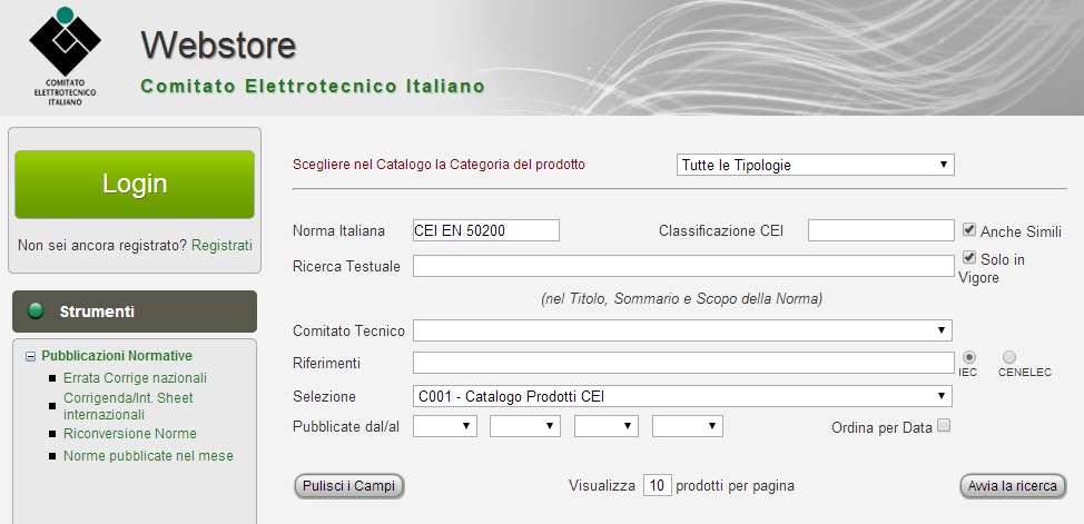
All the relevant documents are available at the CEI Webstore network service, where you can find all the CEI, CEI-UNEL and other publications issued by the Italian Electrotechnical Committee (IEC).
Recommendations for the use of electrical cables
For the proper use of electrical cables in low voltage is good that the designer adopt and prescribe (but especially the installer puts in place) the following recommendations:
- The cables must be suitable for the service conditions specified by the manufacturer. They must be adequately protected from external agents such as excessive heat, water, chemicals, mechanical stress, flora and fauna. Regarding the domestic power supply, you should keep in mind that the kitchen is an insidious local because of the presence of water, flames and metal equipment such as sinks and various household appliances. Thus, even if the standard CEI 64-8 does not require special precautions for the construction of an electric plant in this place, the prescription or use of unsuitable cables can result very dangerous for the safety of persons over time.
- The cables must not be damaged by fixing systems, during laying, transport and handling operations, or during storage. They should not be subjected to excessive stresses, crushing, abrasion, twisting and bending angles that can damage the insulation, especially at low temperatures. For a proper use of various types of cable according to the method of installation and environmental conditions, it is appropriate to refer to the characteristics and conditions of employment that the manufacturer provides with an appropriate data sheet.
- Regarding the current capacities, in the absence of technical data supplied by the manufacturer, refer to CEI UNEL 35024, 35026, 35027 and CEI 20-21, 20-42. If an overcurrent occurs in the cable for long times, this should be taken as the current used in continuous service. In the event of a short circuit, the I2t energy propagating through the protection device, must not cause damage to the cable and/or any media of the cable.
- During the construction of canalizations with protective tube, the designer must pay particular attention to the coefficient of cramming, i.e. the inside diameter of the pipe must be at least 1.3 times the diameter of the circle to the wiring harness in it. This is because the tube must be large enough to allow you to unthread and rethread the wires in it with ease and without damaging the cable. It is a good practice that the location of tubes, both on sight and underground, does not requires more than two 90 degree bends, a too long path with a greater number of curves. This affects the correct installation of the cables and especially promotes an excessive increase in the internal temperature reducing over time the capacity of the cables. For any abrupt deviation due to the wall structure, or derivation from the main line to the secondary line, and especially for each room, the pipeline should be stopped with appropriate junction boxes or manholes. If in the same room it is expected the existence of circuits belonging to different electrical systems, they must be protected from different tubes and run to separate boxes. It is acceptable to place the cables in the same conduit and boxes, as long as they are insulated for the highest voltage and cassettes are fitted with fixed dividers.
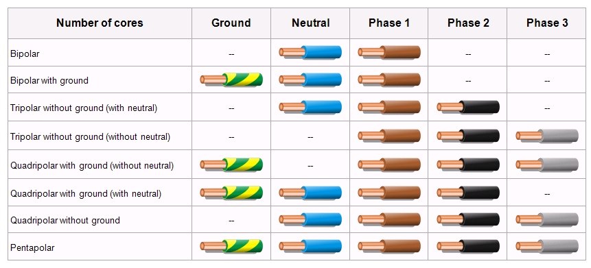
- The use of different colors of the insulation of the conductor is required by the table UNEL CEI 00722 and CEI 16-4 “Identification of conductors by colors or numeric codes” and CEI 16-6 “Code for designation of colors for the conductors identification”. Regarding the low voltage cables, the blue color (BU) must be used only and exclusively to locate the neutral conductor. The yellow-green color (GNYE) must be used only to identify the ground wire and/or the safety wire and/or equipotential wire.The colors black (BK), brown (BN) and gray (GY) are recommended for identify the phase conductors . The colors, in addition to being part of the entire mass of the protective coating, can also be coated only “superficially” the sheath of the cables, for example with insulating tapes appropriately colored and uniformly distributed.
- The cables which are not suitable for outdoor installation, shall be stored in a dry environment, while those suitable for outdoor installation, if stored outdoors, shall have the ends sealed to prevent the moisture penetration. The storage of cables should be at a maximum temperature of 40 ° C.
