With this latest article, Bruno Orsini left us a great gift of his experience. I hope that his great passion for electrical engineering can conquer you like he conquered me.
Goodbye Bruno. Fabio
Introduction
With this article to completion of the previous one “The domotic electric system: the technological evolution of the traditional electrical system” I intend to describe, solely for the purpose of completeness and without claiming to want to dictate any rules. The designer must remain free to choose any other procedure, and technical solution. In this article, I describe the realization of a home automation system of medium level with the most common automation functions such as load management, alert for flooding and gas leaks, lighting, intrusion detection, blinds and shutters motor control. All of this is made possible by the universal standard Konnex system. But before discussing about the actual construction, a brief description of the various devices is necessary.
The components of a Konnex domotic system
The components of a standardized KNX (Konnex) home automation system are highly dependent on market strategies of the various manufacturers that make products with different features. Thus, it can happen that a Schneider device Motion Detector can have specification and design totally different from one of the ABB, even though.the communication system are exactly identical and replaceable. Another example could be a button interface, depending on the manufacturer, it can be used either to connect the switches and/or buttons and/or sensors and/or signaling contacts, or even for driving low-consumption LEDs. Thus, at the design stage, you have to know very well the catalogs of the various manufacturers in order to use the devices that best suit your project needs.
Practically all devices Konnex, available in the market, are divided into the following categories:
System devices are those components with auxiliary tasks that are necessary to operate the system as:
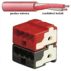
- twisted pair with E/GM red/black terminal that allows the connection of up to four pairs of conductors with quick coupling. In addition, it allows device replacement without interrupting the bus connection and is used as a branch terminal inside of recessed boxes ( see Fig 1 );
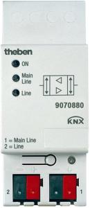
- the line or area coupler or area, that has the function to connect a line or an area to the system. It mainly performs a galvanic separation in a way that a possible electrical failure of a device does not compromise the functioning of the entire system ( a Theben coupler is shown in Fig.2);
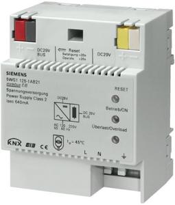
- the power supply generates and controls the DC voltage of the bus line connecting the devices. The more sophisticated types are provided with a supply reel to decouple the power supply from the bus line allowing to supply two different bus lines and a button for restoring ( in Fig. 3 a Siemens power supply). The choice the current output should be made in function of the maximum number of components to be connected to the bus line; in particular ,160 mA for the connection of 16 devices, 320 mA for the connection of 32 devices and 640 mA for the connection of 64 devices. Practically you should consider 10 mA of absorption for each device connected to the bus line;
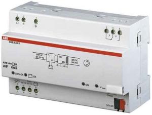
- the emergency power supply is a small group of continuity for the power supply of the bus line in case of temporary absence of the electrical network. Typically it is contained in the power supply ( in Fig.4 an ABB power supply with an input for battery is shown);
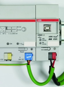
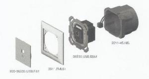
- the data interface for connecting a programming device and diagnostics is a device with a serial port that allows connection to a computer. Thus, you can make, via ETS software, programming or diagnostics of the system. It can be installed at any point of the system and is available on the DIN rail and recessed box. Figure 5 shows an example of connection between a power supply and an ABB USB interface on a DIN rail with the use of a terminal of the KNX Dehn type BT24 equipped with an overvoltage limiter. Figure 6 shows an example of a recessed data interface;
- the infrared remote control with multiple channels allows the remote control of devices such as presence detectors, buttons for roller shutters, blinds, curtains, etc.
Input devices are the electronic interfaces to which input can be connected to the control devices required to implement the functionality of the system. According to the input, you can use these types of device:
- 230 V binary, for connecting devices supplied with mains voltage and with open/closed functionality such as buttons or switches;
- security low voltage binary, for connecting devices without the presence of voltage and with open/closed functionality such as switches, buttons, door contacts, auxiliary contacts;
- analog inputs, for connecting devices that provide a signal in the form of voltage or current such as the sensors.
You can distinguish them as follows:
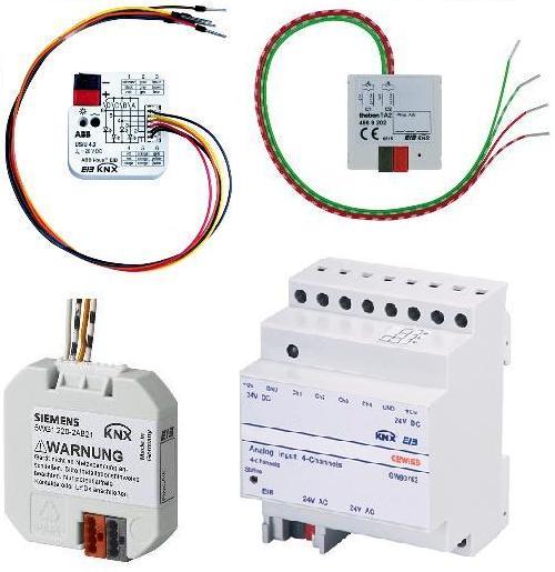
- multiple channels interfaces are BCU units for the connection of the functional units such as buttons or signals coming from the various sensors. They must be installed in the immediate vicinity of the relevant functional units, and if necessary, at a distance not more than seven meters. Figure 7 shows some types of multiple channels interfaces.
- sensors are functional units which carry out, in a logical or analogic way, several functions of detection and measurement of physical quantities such as wind, temperature, humidity, gas, etc. In general, any device implements a single function such as the detection of the brightness of the environment in which it is placed. But there are also models, available on the market, that combine more sensory systems. They can simultaneously monitor various physical quantities. The sensor is a device that must be evaluated with great care in the design phase, especially in complex plants. In fact, its composition and therefore its use can be very variable, from a simple sensing element that is directly connected to an input device, to a device including actuator as the case of a thermostat. Also magnetic contacts are part of the family of sensors and they are used for monitoring doors and windows. Other sensors are the photoelectric cells, the rope contacts for the blinds, the twilight, the contacts in vibration for the control of glass breakage and protection of safes , the optical smoke detectors. In Fig. 8 some types of sensors are shown.
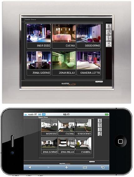
- touch-screen displays are used for the display, the command and control of the plant. The various areas of the apartment might be displayed in with the use of special software. Figure 9 shows a Gewiss screen with application for remote control by i-phone.
Output devices are devices that receive the signals from the input devices through the bus connecting. They interface the electrical network with various functional components type lamps, motors, solenoid valves, etc. The ways in which you can connect the electrical load are:
- binary connects or disconnects the electrical load by means of a relay or an equivalent circuit;
- analogic provides a variable voltage or current for controlling devices not Konnex;
- dimmer provides a variable voltage or current with which an electronic regulator varies the voltage across the load. It is mainly used for adjusting light intensity of the lighting equipment;
- DSI is used for digital control of devices with electronic regulator such as DALI lighting.
You can distinguished them as follows:
- Individual actuators are used to control a single load. They are generally available for nominal currents of 10 A and 16 A;
- Combined actuators are used for the control of multiple loads;
- Dimmer actuators are used for adjusting the light intensity of the lamps.
Functional devices are all the devices that are part of the catalog of the manufacturer and that perform specific functions.
Scenarios are sequences of operations who create a predetermined event using a single action control. For example, you can turn on more light fixtures simultaneously, or exiting from home, you can lower all the shutters, turn off all lights and disconnect power to all sockets with excluding those priorities. This type of sequences can be accomplished either as a result of certain detections sensors, such as switching on a given path of light with a presence sensor, winding tends as result of monitoring of the wind, or remotely through GSM communicator such as the activation of the heating during the way back to home, or the activation of irrigation of plants or garden.
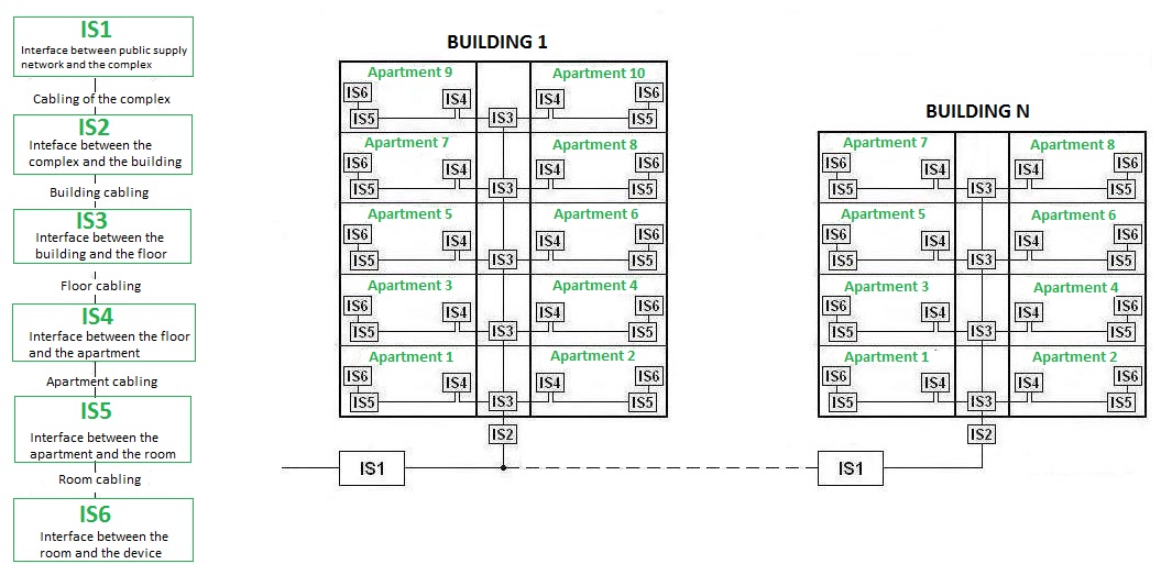
Installative spaces. You need to define them in order to define the path of the bus line and consequently a proper distribution of pipes. EN 50090-9-1 introduced, with an appropriate classification (see Fig. 10), the concept of installation space IS (Istallative Spaces), ie various types of containers inside which can be inserted into both home automation devices and the traditional ones. In practice, the IS are made of distribution panels, junction boxes, boxes for modules relative to the different devices that must be installed.
- IS1 may coincide with the external point of delivery of the electrical distributor or of telecommunication services;
- IS2 may coincide with the main electrical panel building;
- IS3 may coincide with a junction box of the riser column or the electric panel for a floor;
- IS4 may coincide with the electrical panel of an apartment;
- IS5 may coincide with a junction box;
- IS6 may coincide with a box for modules.
A practical example
You have been commissioned to design the home automation with a KNX standardized system for an apartment with a floor area of about 180 m2 . The apartment is under construction as a part of a condominium complex, and its the planimetry is provided.
After you have implemented and analyzed the requirements of the customer and following that the home automation project is commissioned after the completion of the primary building works (therefore you are unable to build a special technical room and/or specific skylight well), you have to decide:
- to match the installation space IS4 with the control unit Q1 consisting of a switchboard recessed Schneider Electric model Pragma with 96 modules (4×24), code PRA26424;
- to use the same installation space IS5 and IS6 both for the distribution of the bus line and for the distribution of the driving force but with separate pipes and placing the actuators in the installation space IS5. This is due to the fact that the home automation project is commissioned after the completion of the building works primary and therefore be unable to intervene on the structure such as the creation of a special technical room;
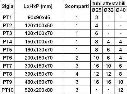
- to use rectangular modular boxes (see Figure 11), instead of round ones generally used in home automation systems Konnex, with the use of any components of a national civil line connected with KNX interfaces with two or four inputs. In case you are using recessed junction boxes, built-DIN type PT8 with four separate compartments, see the Table 1. If you are using rectangular modular boxes up to 6 modules, this choice offers a better aesthetic solution because it allows you to group better the outlets. In fact, a round box allows the installation of only a single schuko;
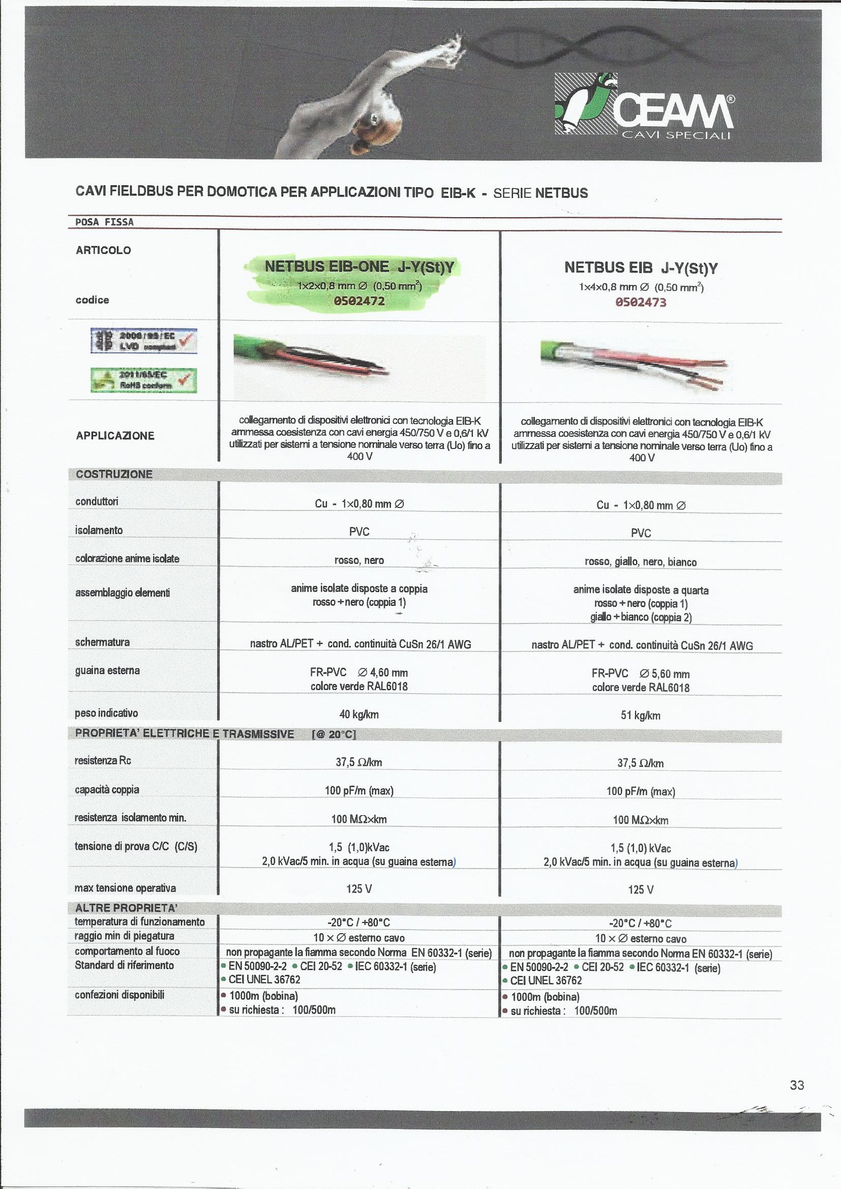
- to use the cable bus CEAM 1x2x0,8mm, code 0502472, which is KNX certified with technical characteristics allowing the installation in the same pipes and junction boxes of the driving force ( see Figure 12);
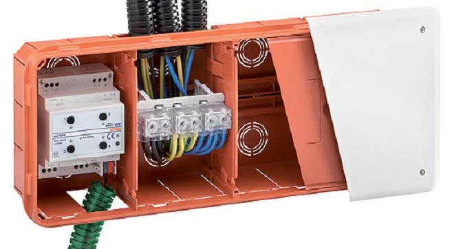
- to dedicate an installation space IS5 for each environment, intended for the control of the associated actuator devices and its driving force. Figure 13 shows an example of a junction box PT8 Gewiss with actuator and the terminal for the distribution of the driving force;
- to use relay actuators capable of withstanding the same current of the power line, for example 10 A, even if the characteristics of the output control devices are able to adapt to the characteristics of the load as a low-consumption LEDs. This design solution ensures a high degree of safety, especially in case of a future change of the characteristics of the electric load, as in the case of replacement of lED lighting equipment with other more powerful. In this case it is likely to exceed the current limit of the output device with a consequent damage to the device itself and the need for a technical intervention for reprogramming the command. In the case of the relay actuator device, in case of failure to excessive load, it is sufficient to replace the relay device without requiring reconfiguration;
- to position one installation space IS6 near the general water tap and gas tap in order to enable the control of the relative solenoid valves as a result of a flood alarm and gas leaks;
- to divide the bus connection in two lines (although technically it is possible to use a single bus line as it is not exceeded the maximum number of 64 devices), one relative to the living area (kitchen, living room, bathroom, balcony) and one to the night area (room, hallway, bathroom). This in order to ensure a greater usability of the system following any maintenance or future changes with increase of the number of devices;
- to choose ABB KNX bus devices.

