The STL file
STL (STereoLithography) is a file format widely used in the world around the 3D printers.
An STL file is used mainly to describe the surface geometry of a 3D model. Essentially It contains all the geometric information of the 3D model without any representation of colors, textures and other common CAD model attributes.
An STL file could be both in ASCII and binary format, but binary files are more common since they are more compact. If you open an ASCII (not binary!!) STL file with any text editor (i.e. Notepad++) you can easily analyze how the data, representing the 3D model, are stuctured.
Any STL file begins with this line:
solid name
name is an optional string (though if name is omitted there must be a space after solid).
The file continues with a list of triangles (facet), each represented in the following format
facet normal ni nj nk
   outer loop
      vertex v1x v1y v1z
      vertex v2x v2y v2z
      vertex v3x v3y v3z
   endloop
endfacet
n is the normal to the triangle surface (facet normal) and its three vertices are indicated with the vn vectors. The facet normal should be a unit vector pointing outwards from the solid object. All these triangles will compose the surface of the 3D model. Then, at the end of the file, the line:
endsolid name
ends the STL structure.
Some general design rules
If you are designing a 3D model which will be used to create a rendered image or in a video game, you don’t need to go mad if the model is not feasible in reality. Often, in this cases, many 3D scenes contain objects which are made up by only those elements that should be visible, the other hidden elements can be omitted.
Thus the STL file could contain some topology issues, bad meshes and duplicated vertices as well. But if you need to print this model with a 3D printer, the situation is completely different!
A 3D printer user normally uses several software for creating his 3D models. For example, OpenSCAD and Blender are open-source and free software, but there are many other professional CADs distributed as commercial products.
Then you need to use a slicing tool (such as Skeinforge or Slic3r), in order to compile the 3D geometry to a set of G-Code instructions, required to generate the toolpath for the extruder.
Finally you turn your 3D model in a solid object with a 3D printer controlled by a further program, such as Printrun, Cura or RepetierHost.
Watertight objects (no holes in the mesh)
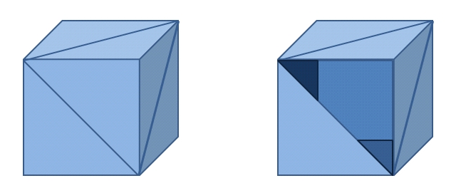
In this chain of steps you always have to keep in mind that you are working with real and solid objects! Thus 3D models for 3D printing must be “watertight” to be printable. While you are designing your model, think of the possibility of filling your object with water. Any drop of water must not drain out.
Normal vectors orientation
Another important thing is the orientation of the normal vectors of the triangles within the STL file. All the triangles should have their normals pointing in the correct direction. If your model contains an inverted normal, the 3D printer cannot determine the inside or the outside of your 3D model.
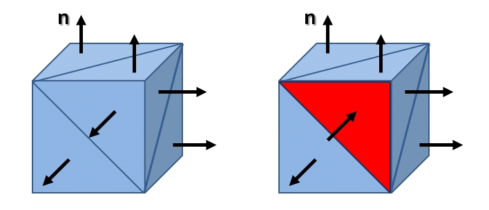
Remove errors in the Mesh surface
Often, especially when the 3D model is quite complex, there could be some errors in your model such as duplicates or redundant elements (extra lines or faces).
An object is a collection of triangles that are connected to each other. Normally, all of these triangles define the surface of the object. Other triangles are redundant or unnecessary (not belonging to the surface).
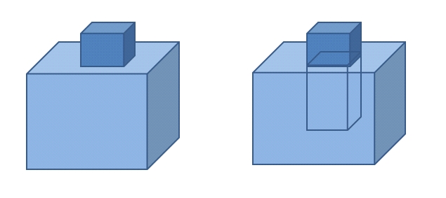
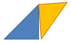
All edges of each triangle should be properly connected to each other. Otherwise they can form holes, overlapping or cut surfaces . In this case they are called “bad-edges“.
In an STL file there could be some intersecting triangles cutting each other.
Comply with specification of your 3d printer
You need to pay attention to the maximum size of the objects that you can print and their wall-thickness as well.
Fortunately, and somewhat due to the fact that this kind of errors is very common, there are a lot of solutions to optimize and check the STL files (that is the 3D model) before a 3D printing. The most common are Netfabb, Rhino (the Mesh Repair functions), Willit3DPrint, Meshmixer.
Once your STL file has been tested, and if necessary fixed, you can slice your model to generate the g-code and finally print it.
How to check and repair an incorrect STL file?
Certainly the vast majority of professional products have embedded within them a whole range of tools for this kind of operation. Some free open-source application are beginning to offer similar services as well. But the solution that I prefer is to optimize and repair freely with a Web service (without installing anything on your PC!!!).
In this post i will show you, two of these web services (free), they can be used in sequence and they are an ideal solution for those who want to set up an analysis to the STL file before sending it to print.
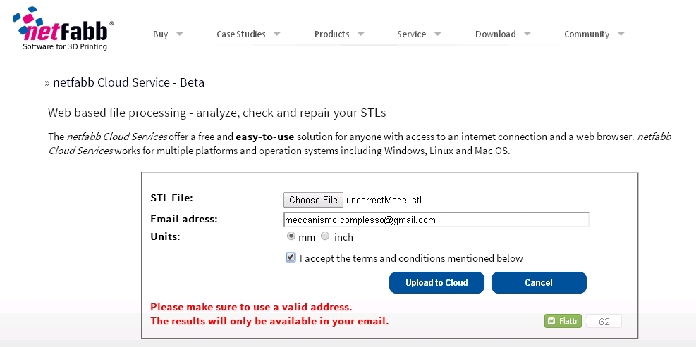
Netfabb Cloud Services is a free product for the world of 3D printing. It can be used form any web browser running on any platform and any operating system. Simply go to the web page , upload the STL file, enter your email address and within few minutes you will receive an email with the a link to download the repaired STL file.
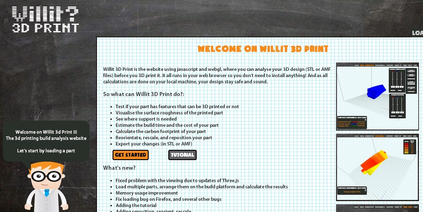
Another Web service is Willit 3D Print. This website uses JavaScript and WebGL for visualizing your 3D Model and analyzing the STL file you uploaded.
You will find its analysis of the STL file very useful for practical reason. In fact, after you uploaded the STL file you can obtain a lot of useful information.
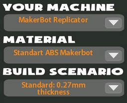
Before starting with the analysis of the uploaded file, the site asks you to set the 3D printer model, the material used and the thickness.
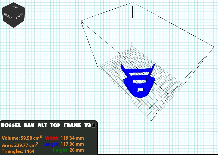
According to these values, the results of the analysis will vary. After some seconds of calculations the web page will show the 3D model enclosed in a box. The box is the volume in which the 3D printer can operate. At the bottom left there is a label reporting some useful values such as the size of the object, its volume and the area of its outer surface.
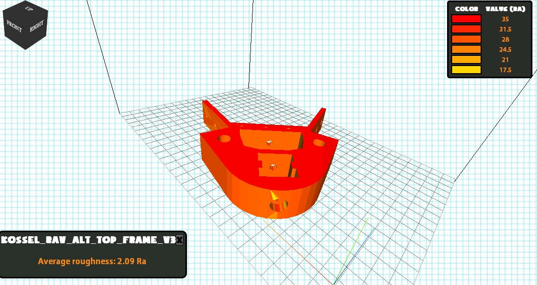
From this scenario, first, we can examinate the 3D model in detail rotating or scaling it with the mouse. Then you can use some of the tools that this web application provide. For example, you can analyze the roughness of the model represented by a color gradient.
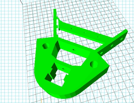
Then it is possible to ask to the application if the model can be printed. After some seconds of calculation you get a good result if the whole objecy is reported in greed (as below). If some part is in red, then that area probably could not be printed.
And last but not least, this web application can provide you some information about the build time and cost.

